The magnetic flux leakage inspection method is used for non-destructive and non-contact detection of fractures in the prestressing reinforcement of prestressed concrete structures. The method has been developed and used since the 1980s by the MPA University of Stuttgart (then FMPA/ Otto-Graf-Institute). Our experts can draw on decades of experience. We are constantly refining the magnetic leakage field measurement in order to be constantly better able to meet the challenges of the future.
Prestressed concrete allows building civil engineering structures that bridge large spans with elegance, durability and, at the same time, high structural strength. Almost 70% of all bridges on German federal highways are therefore made of prestressed concrete. The building material is also used in many other engineering structures, such as gymnasiums, industrial buildings, event locations, train stations and airports, trade fairs, theaters and many more.
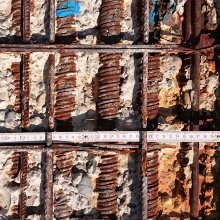
The load-bearing capacity of prestressed concrete depends significantly on the condition of the tendons. If these fail, the stability of the structure may be compromised. Since the steel is embedded in the concrete, a visual inspection is not sufficient to reliably assess the condition.
In modern prestressed concrete, the tendons are reliably protected from corrosion and accidental mechanical damage by the surrounding concrete. However, prestressed concrete structures should be specifically examined if any of the following hazard factors apply. Our experts will be happy to advise you on this!
Tempered prestressing steels
Until 1993, tempered prestressing steels were partly used in which sudden failure can occur (St 145/160, trade names Neptun and Sigma, and St 140/160, Hennigsdorfer Spannstahl, see also here). These bear the risk that the failure is not announced beforehand by noticeable cracking on the concrete surface or signs of corrosion. Up to the 1970s, little supplemental steel reinforcement was provided, since it was assumed that there would be no need for it in prestressed concrete structures. As a result, force redistribution in the event of tendon failure is often only possible to a limited extent.
If your prestressed concrete structure was built during the period in question, you can ideally obtain the information on the prestressing steel used from the record of the structure or you will have to have a piece of the steel tested in the laboratory.
Corrosion
Poor corrosion protection and water-accessible cracks significantly increase the probability of fracture of all prestressing steel grades. In particular, if chlorides (road salt, sea air) can penetrate the concrete with the water and if cladding tubes are not fully grouted, there is a higher potential for damage.
When inspecting your structure, pay particular attention to water drainage marks, defective surface seals, and evidence of existing corrosion damage such as flags of rust, cracks, or concrete spalling.
Mechanical damage
Time and again, prestressed concrete girders are carelessly punctured in the area of the prestressing steel in order to subsequently fasten structural elements to them. The inherently good protective effect of the concrete does not help in this case.
Contact us if you notice unusual drilling in your prestressed concrete girders or suspect that a prestressing steel has been damaged for some other reason.
Fatigue and overload
The ever-increasing traffic loads on infrastructure buildings can cause prestressed concrete to age prematurely compared to design. Coupling joints have proved to be particularly critical in this respect in the past. However, damage to tendons can also be caused by isolated events, such as static overloads, vehicle impact, fire, earthquakes, floods and extreme storm events.
Alumina cement
In the years 1952 to 1963, the binder alumina cement was sometimes used in the construction of prestressed concrete elements. If the relative humidity in the area of the load-bearing structure permanently exceeds 70% or if water can reach the prestressed concrete due to inadequate sealing, there is a risk of collapse. Damage to the prestressing wires can usually not be detected visually beforehand. It is recommended to examine such structural systems with a magnetic stray field measurement.
Owners, holders, operators, and other parties responsible for the construction of a prestressed concrete structure are legally obligated to ensure the structural stability of their buildings at all times. Yet, in order to preserve the value of the structure or property and to maintain its use, defects in the load-bearing structure should always be identified and repaired in good time.
The applicable codes of practice result in a statutory inspection obligation for every long-span superstructure. These include, among others, the bridge inspection according to DIN 1067, the regular structural inspection for buildings according to VDI 6200 and the inspection of railroad bridges according to DB guideline 804.8002.
Depending on the rules and regulations and the type of structure, a detailed, manual inspection must be carried out at intervals of 6 to 15 years, even if the building condition is good.
An additional inspection is recommended after exceptional events, conversion work, changes of use or modernization. If defects have already occurred, an object-related damage analysis must be carried out to assess stability.
In its communication of August 10, 1992, the German Institute for Construction Technology (now DIBt) recommends that prestressed concrete structures be examined for prestressing steel fractures during structural alterations or changes of use. Corresponding examinations should also be carried out if there are obvious deficiencies in the prestressed concrete structure, in the case of the occurrence of locally increased cracking and if there is very little concrete cover. In particular, inspections are advisable if the components are exposed to elevated humidity or aggressive environments (E. Wölfel: Einzelne Spannbetonbauteile möglicherweise durch verzögerte Spannstahlbrüche gefährdet. Mitteilungen IfBt 4/1992, 23(4), S. 114-115, 1992. Provided with the kind permission of the Deutsches Institut für Bautechnik (DIBt), www.dibt.de).
We can reliably detect fractures in prestressing steels of prestressed concrete structures with magnetic flux leakage inspection. The method is also known as magnetic stray field measurement, prestressing steel fracture localisation and remanence magnetism method (RM method). The testing method is completely non-destructive and thus offers you the possibility to examine even large areas to 100%. You receive as result a statement on the actual condition of the tendons, which can be used for a recalculation, an estimation of the residual load capacity of the structure or for the planning of repair measures.
Magnetic flux leakage inspection is the only comprehensive and thus efficient examination technique for the assessment of prestressing steels.
In August 2017, a position paper was published by the DGZfP, which was prepared with the cooperation of the Material Testing Institute of the University of Stuttgart in the subcommittee "Magnetic Flux Leakage Inspection". In the memo, the state of the art in this field is described.
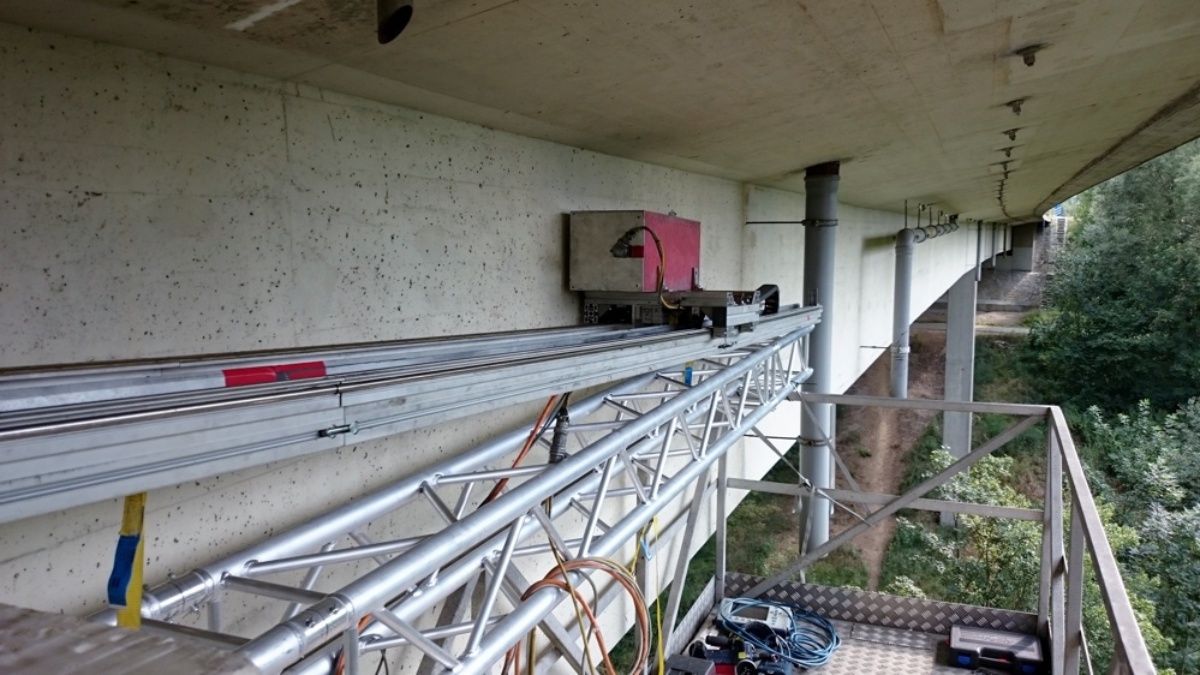
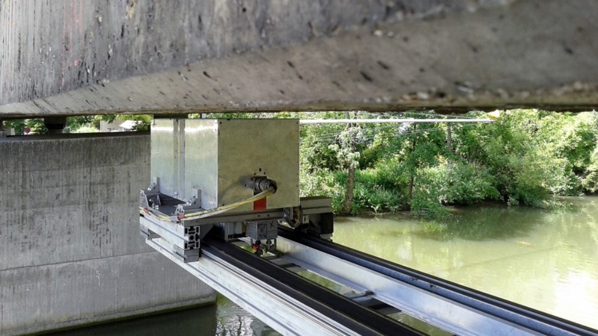
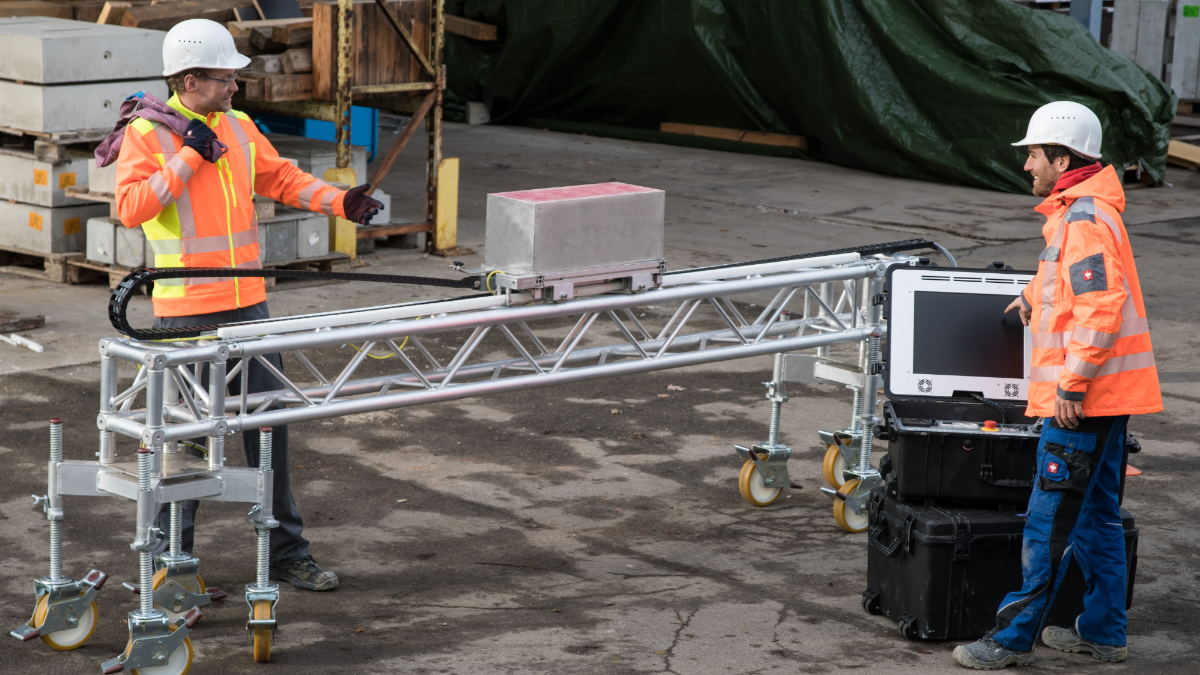
In magnetic flux leakage inspection, the examination head, which contains an electromagnet and magnetic field sensors, is driven along the prestressing reinforcement on a rail. It magnetizes the prestressing steel to be tested. At a fracture point, a magnetic leakage flux emerges, which is detected at the element surface by the magnetic field sensors.
The magnetic flux leakage inspection can be carried out on prestressing steels both in the immediate bond (precast prestressed concrete components) and in the subsequent bond (in grouted ducts).
Preparation of the measuring areas by the client
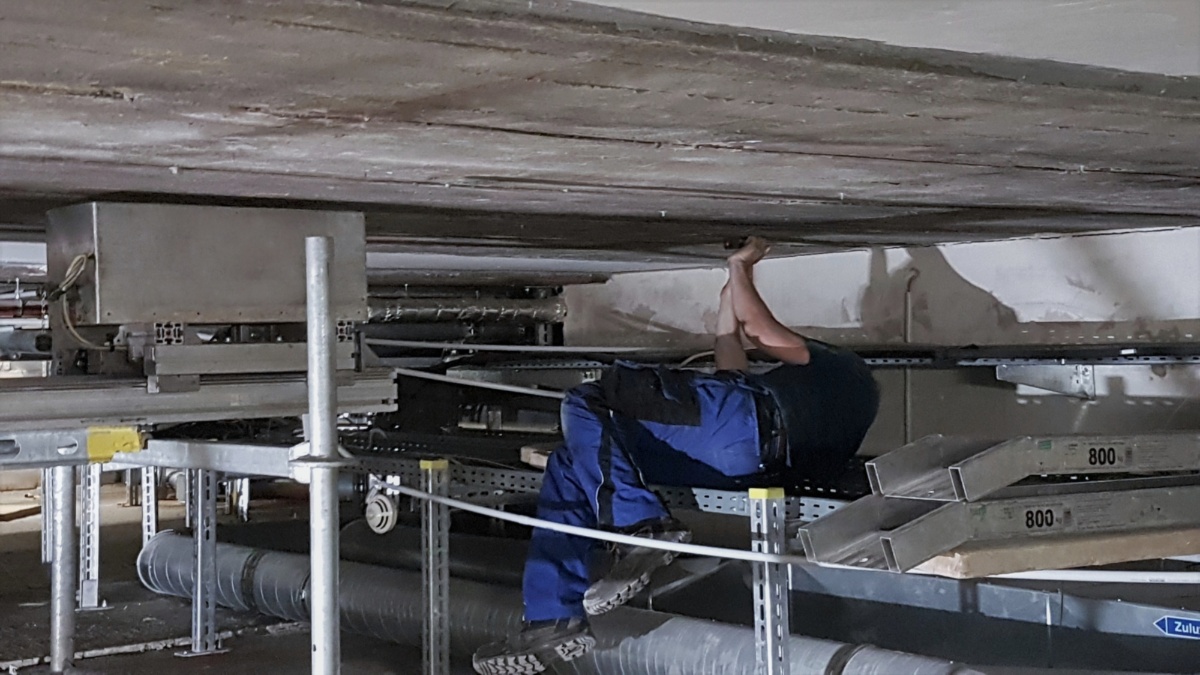
Before magnetic flux leakage inspection can begin, all structural parts to be examined must be made accessible. This includes the dismantling of suspended ceilings, lighting, technical building equipment and other mounted components. During the measurement, it must be possible to move the magnet continuously along the test area at a small distance from the concrete surface. Please contact us to determine the extent to which these works are necessary for your particular testing task.
A voltage source (230 V, 16 A slow-blow, Schuko power plug) must be available in the test area for connecting the measuring instruments and lighting.
Locating the tendons
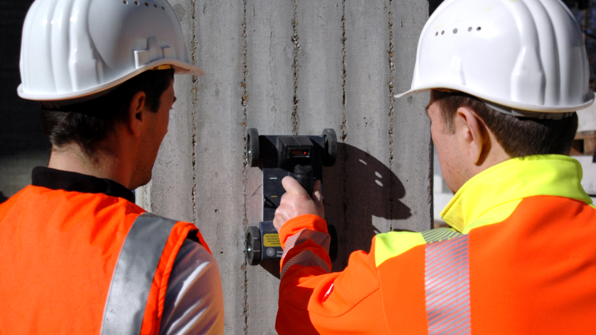
Especially in the case of tendons in ducts, their positions and exact paths are often unknown. But also in plate and slab cross-sections, the position of the tendons is not obvious. Before the actual inspection, we therefore determine the exact course of the tendons in the area to be inspected non-destructively using radar and mark them on the concrete surface.
Access equipment
Measurement upwards: Roof girders and longitudinal bridge reinforcement
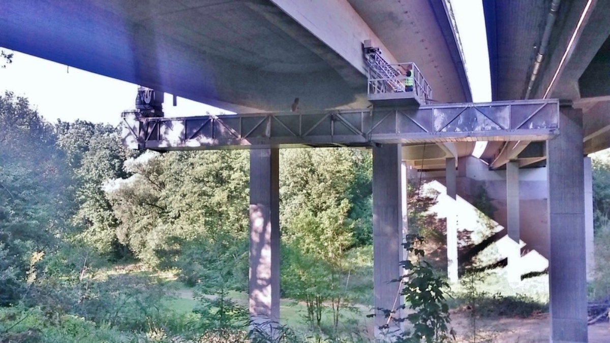
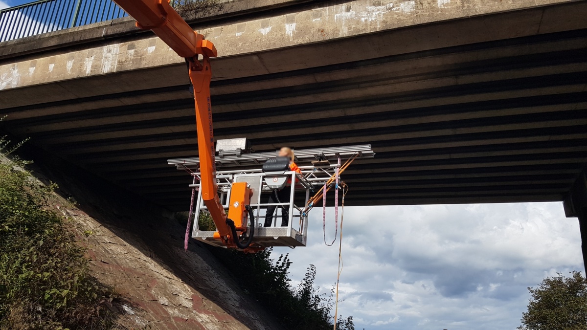
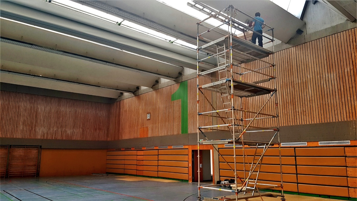
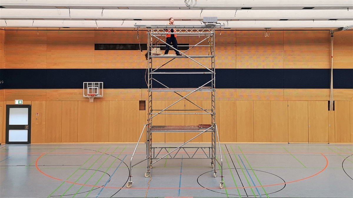
For an inspection, the girders must be accessible by hand. For large bridges, bridge soffit devices are usually used. When measuring roof girders, we usually employ an elevating work platform or rolling scaffold. Generally, access via a lifting vehicle enables measurements to be carried out more quickly, as there is no need to move the measuring instrument manually. However, the prerequisites regarding dimensions, outreach, load capacity, maneuverability and trafficability of the underground must be met before the equipment can be applied.
If the access technology is provided by you, we ask you for a timely coordination concerning the technical details.
Measurement downwards: Roadway slabs
When measuring downwards, e.g. when testing the transverse prestressing in box girder bridges, no access equipment is required. The measurement setup is placed directly on the road. To reduce the distance between the magnet and the prestressing reinforcement, it may be necessary to mill off the pavement before the measurement. It is therefore often a convenient option to carry out a magnetic flux leakage inspection in the course of a waterproofing or pavement rehabilitation project.
Execution
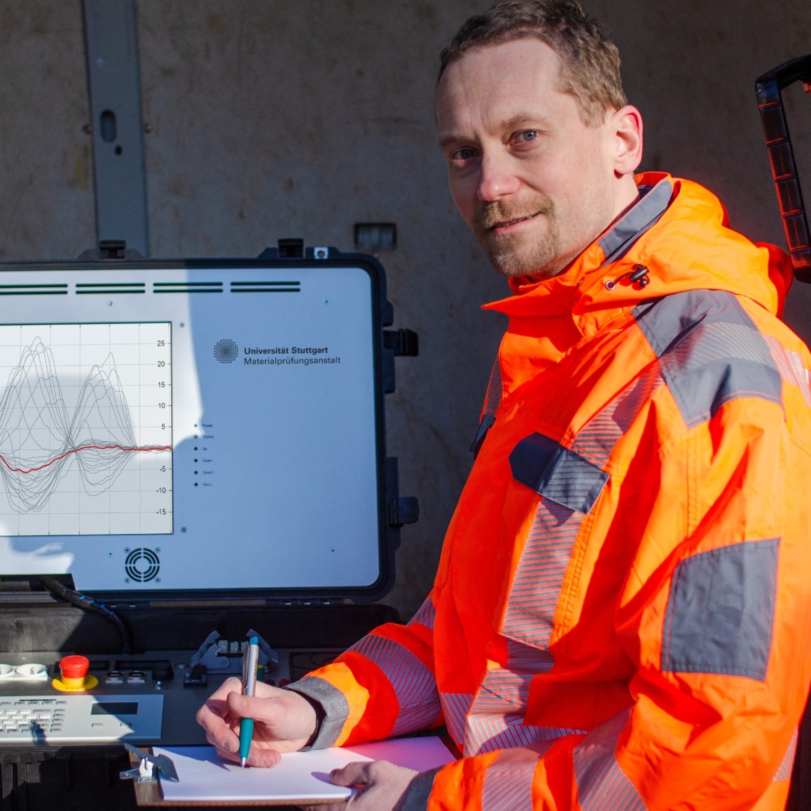
Once the magnet has been placed in position against the structural element, the measurement is quick. In several automated measurement runs, we vary the magnetic field strength to minimize the influence of the supplement reinforcement on the result. We measure the prestressing steel magnetization in the active field and the remanence magnetization. This provides you with an optimum statement on the prestressing steel condition in the tested areas.
For larger components, we can chain together several individual measurements with sufficient overlap. A condition assessment of the prestressing steel with regard to prestressing wire fractures is thus possible over the entire length without the need to install an elaborate rail system.
We also measure at night or on weekends if your construction schedule should require it. In case of imminent danger, we can usually act for you at short notice.
Verification
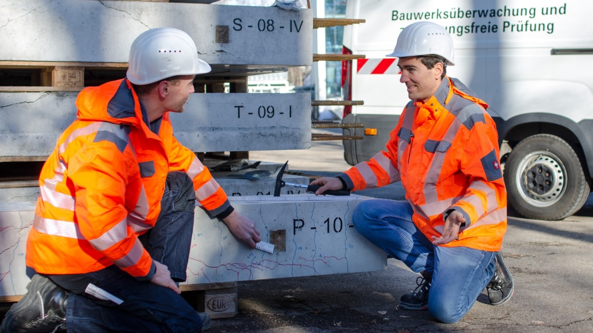
After the inspection, we will send you the positions at which we have detected fracture indicators. For verification, you will have to make small openings in the structural members at these points. We will be happy to provide expert assistance in carrying out the openings and in assessing the exposed prestressing wires.
Permits and traffic safety
For a measurement in the area of public traffic routes, the necessary permits must be obtained in advance. These include, for example, a traffic law order (roads), an operating and construction instruction "Betra" (railroads) or a stream and waterway police permit ( waterways). If necessary, we can apply for these permits in consultation with you. Please note that there can sometimes be quite long periods of time between the application for the permit and the execution of the measurement.
When working in the area of flowing traffic, special safety measures must be taken by the client.
We have successfully used the magnetic flux leakage inspection method on hundreds of constructions. To ensure that your project will also be a success, we ask you to observe the following application limits. We will be happy to advise you on your specific request.
- Only prestressing tendons up to a concrete cover of approx. 20 cm can be examined with a high degree of reliability. We can simulate the exact reinforcement situation in the laboratory to further increase the reliability of the results.
- In the case of a partial failure of individual wires in prestressing strands, the intact wires shield the magnetic flux leakage field. Depending on the other influencing factors, prestressing wire fracture detection is possible from a cross-sectional reduction of about 15 to 20% of the total cross-section. For this reason, cracks in prestressing rods can also not be detected.
- In most cases, magnetic flux leakage inspection can only provide information on the first tendons close to the surface, since strands at a greater depth are magnetically shielded. Spatially resolved single wires can be an exception.
- In the end zones, non-inspectable sections remain over a length of approximately 50 cm each. These cannot be measured, because, for physical reasons, uniform magnetization cannot be achieved here. Statements on the state of the prestressing steel immediately adjacent to an end anchorage (prestressing head) are also not possible.
- Special arrangements of the supplement reinforcement and incorporated steel parts in the measurement area can lead to false indications. We will therefore provide you the position of fracture indicators after the measurement, which must be verified by local openings.
- Metal-laminated waterproofing sheets and close meshed reinforcement may prevent the location of the prestressing tendons by radar. If the position of the tendons is not known from plans or if no full-field measurement can be carried out, the magnetic flux leakage inspection is not effective.
Magnetic flux leakage inspection in action
DGZfP Positionspapier. Magnetische Verfahren zur Spannstahlbruchortung. Deutsche Gesellschaft für Zerstörungsfreie Prüfung (DGZfP), Unteraussschuss Magnetische Verfahren zur Spannstahlbruchortung, Berlin, 2017. Link zum Volltext (pdf, 1,3 MB)
DIN 1076:1999-11. Ingenieurbauwerke im Zuge von Straßen und Wegen - Überwachung und Prüfung. Beuth Verlag, Berlin, November 1999. Bezugsquelle
Bauwerksprüfung nach DIN 1076. Bedeutung, Organisation, Kosten. Dokumentation 2013. Bundesministerium für Verkehr, Bau und Stadtentwicklung (BMVBS), Berlin, 2013. Link zum Volltext (pdf, 3 MB)
Richtlinien für die Erhaltung von Ingenieurbauten (RI-ERH-ING). Richtlinien zur einheitlichen Erfassung, Bewertung, Aufeichnung und Auswertung von Ergebnissen der Bauwerksprüfung nach DIN 1076 (RI-EBW-PRÜF). Bundesministerium für Verkehr und digitale Infrastruktur (BMVI), Berlin, 2017. Link zum Volltext (pdf, 3 MB)
Richtlinien für die Erhaltung von Ingenieurbauten (RI-ERH-ING). Leitfaden Objektbezogene Schadensanalyse (OSA). Bundesministerium für Verkehr, Bau und Stadtentwicklung (BMVBS), Berlin, 2007. Link zum Volltext (pdf, 0,6 MB)
Handlungsanweisung zur Überprüfung und Beurteilung von älteren Brückenbauwerken, die mit vergütetem, spannungsrisskorrosionsgefährdetem Spannstahl erstellt wurden (Handlungsanweisung Spannungsrisskorrosion). Bundesministerium für Verkehr, Bau und Stadtentwicklung (BMVBS), Berlin, 2011. Link zum Volltext (pdf, 1 MB)
Richtlinie zur Nachrechnung von Straßenbrücken im Bestand (Nachrechnungsrichtlinie). Bundesministerium für Verkehr, Bau und Stadtentwicklung (BMVBS), Berlin, 2011. Link zum Volltext (pdf, 2,3 MB)
Richtlinie zur Nachrechnung von Straßenbrücken im Bestand (Nachrechnungsrichtlinie). 1. Ergänzung. Bundesministerium für Verkehr, Bau und Stadtentwicklung (BMVBS), Berlin, 2015. Link zum Volltext (pdf, 1,4 MB)
Hinweise für die Überprüfung der Standsicherheit von baulichen Anlagen durch den Eigentümer/ Verfügungsberechtigten. Konferenz der für Städtebau, Bau- und Wohnungswesen zuständigen Minister und Senatoren der Länder (Argebau), Bauministerkonferenz, 2006. Link zum Volltext (pdf, 0,1 MB)
VDI 6200:2010-02. Standsicherheit von Bauwerken. Regelmäßige Überprüfung. Verein Deutscher Ingenieure (VDI), Düsseldorf, 2010/2015. Bezugsquelle
Richtlinie für die Überwachung der Verkehrssicherheit von baulichen Anlagen des Bundes (RÜV). Bundesministerium für Verkehr, Bau und Stadtentwicklung (BMVBS), Berlin, 2008. Link zum Volltext (pdf, 0,8 MB)
Richtlinie 804.8001. Inspektion von Ingenieurbauwerken; Allgemeine Grundsätze. DB Netz AG, Frankfurt am Main, 2020. Bezugsquelle
Richtlinie 804.8002. Inspektion von Ingenieurbauwerken; Eisenbahnüberführungen. DB Netz AG, Frankfurt am Main, 2020. Bezugsquelle
Richtlinie 804.8003. Inspektion von Ingenieurbauwerken; Überbauungen von Betriebsanlagen und sonstige Überbauungen. DB Netz AG, Frankfurt am Main, 2020. Bezugsquelle
Richtlinie 804.8004. Inspektion von Ingenieurbauwerken; Sonstige Ingenieurbauwerke. DB Netz AG, Frankfurt am Main, 2020. Bezugsquelle
Richtlinie 805.0104. Tragsicherheit Eisenbahnbrücken; Grundlagen für die Nachrechnung; Messtechnische Bauwerksuntersuchungen. DB Netz AG, Berlin, 2021. Bezugsquelle
Richtlinie 805.0202A01. Tragsicherheit Eisenbahnbrücken; Tragsicherheit bestehender Eisenbahnbrücken mit spannungsrisskorrosionsgefährdeten Spannstählen. DB Netz AG, München, 2021. Bezugsquelle
Arbeitshilfe zu Richtlinie 805.0202A01. Nachrechnungskonzept für Bauwerke mit spannungsrisskorrosionsgefährdeten Spannstählen. DB Netz AG, München, 2020. Bezugsquelle
Richtlinie 883.8000. Geo-Monitoring; Grundsätze. DB Netz AG, Frankfurt am Main, 2020. Bezugsquelle
DGZfP Merkblatt B 13. Feuchtemessung im Bauwesen. Deutsche Gesellschaft für Zerstörungsfreie Prüfung (DGZfP), Unteraussschuss Feuchte, Berlin. In Vorbereitung
Hinweise für Eigentümer und Mieter von Wohngebäuden, Wohnungen und Nebengebäuden mit Spannbetondecken mit dem Bindemittel Tonerdeschmelzzement, hergestellt in den Jahren 1952 bis 1963. Bayrisches Staastministerium des Inneren, Oberste Baubehörde, München, 1993. Link zum Volltext (pdf, 4 MB)
Sawade, G. und Menzel, K.: Zerstörungsfreie Feststellung von Spannstahlrissen in vorgespannten Deckenträgern. In: Werkstoffe und Korrosion 40(7), 1989, S. 454. DOI: 10.1002/maco.19890400708
Sawade, G.: Quantitative aspects of the detection of ruptures of prestressed steels in concrete beams using the magnetic flux leakiage measurement method. Otto-Graf-Journal, 2, 1991. S. 287-310. Link zum Volltext.
Sawade, G., Straub, J., Krause, H.‐J., Bousack, H., Neudert, G. and Ehrlich, R.: Signal analysis methods for remote magnetic examination of prestressed elements. In: Schickert, G., Wiggenhauser, H. (Hrsg.): Proceedings of the International Symposium on Non-Destructive Testing in Civil Engineering (NDT‐CE), Berlin, Vol. 2, DGZfP, 1077–1084, 1995. ISBN 3-931381-02-1.
Sawade, G.: Anwendung der Methode der magnetischen Streufeldmessung zur Ortung von Spannstahlbrüchen. DGZfP Berichtsband 66, Vortrag 7, Fachtagung Bauwerksdiagnose, München, 1999, S. 73-81.
Sawade, G.: Numerische Modellierung der magnetischen Streufeldmessung zur Ortung von Spannstahlbrüchen. In: Große, C. (Hrsg.): Werkstoffe und Werkstoffprüfung im Bauwesen. Festschrift zum 60. Geburtstag von H.-W. Reinhardt. Libri BOD, Hamburg, 1999, S. 338-351. ISBN 3-89811-172-5. Link zum Volltext.
Sawade, G.: Mobiles SQUID‐Meßsystem zur Bauwerksinspektion, Teilvorhaben Magnetisierungsvorrichtung und Signalverarbeitung. Forschungsbericht 13 N 7249/3, Bundesministerium für Bildung Wissenschaft, Forschung und Technologie, 2001.
Sawade, G., Krause, H.‐J: Inspection of prestressed concrete members using the magnetic leakage flux measurement method ‐ Estimation of detection limit. In: Große, C. (Hrsg.): Advances in Construction Materials 2007, Springer‐Verlag, Berlin, 2007, S. 639–649. DOI: 10.1007/978-3-540-72448-3
Sawade, G., Krause, H.‐J: Prüfung von Spannbetonteilen mit magnetischen Methoden. Beton‐ und Stahlbetonbau 105, 2010, S. 154‐164. DOI: 10.1002/best.200900075
Sawade, G., Krause, H.-J.: Magnetic flux leakage (MFL) for the non-destructive evaluation of pre-stressed concrete structures. In: Maierhofer, C., Reinhardt, H.-W., Dobmann, G. (Hrsg.): Non-Destructive Evaluation of Reinforced Concrete Structures. Woodhead Publishing, Volume 2, 2010, S. 215-242. ISBN 978-1-84569-950-5, DOI: 10.1533/9781845699604.2.215
Steinfeld, B.: Untersuchungen zur Bestimmung der Nachweisgrenzen der Detektion von Spannstahlbrüchen in Spannbündeln mit der Methode der magnetischen Streufeldmessung. Diplomarbeit, Universität Stuttgart, 2014. Erhältlich auf Anfrage in der Institutsbibliothek.
Villing, J.T.: Detektion von Spannstahlbrüchen mit der magnetischen Streufeldmessung unter Variation physikalischer und geometrischer Parameter. Masterarbeit, Universität Stuttgart, 2022. Erhältlich auf Anfrage in der Institutsbibliothek.
Wilhelm, T., Scheerer, S., Hampel, T., Bauer, T., Müller, M.: Materialuntersuchungen an Hennigsdorfer Spannstahl aus Brückenbauwerken. Bautechnik 92, 2015, S. 93-104. DOI: 10.1002/bate.201400054
Schreiner, M., Sawade, G., Steinfeld, B.: Evaluation of the detection limits for the investigation of strands using the magnetic leakage field method. In: Forde, M.C. (Hrsg.): Proceedings of the 16th European Bridge Conference, Edinburgh, Scotland, 2015, paper 1531. ISBN 0-947664-78-4.
Schreiner, M., Lehmann, F.: Magnetische Streufeldmessung zur Lokalisierung von Spanndrahtbrüchen. Fachtagung Bauwerksdiagnose, Berlin, 2018. Kurzfassung mit Poster.
Lehmann, F.A.: Non-destructive testing and monitoring as elements of building inspection. Otto-Graf-Journal, 19, 2020, S. 119-130. Link zum Volltext
Bauwerkprüfung nach DIN 1076. Bundesministerium für Verkehr und digitale Infrastruktur (BMVI), 18.07.2018 - Video in der Langversion (ca. 45 Minuten) und der Kurzversion (ca. 7 Minuten).
Contact

Frank Lehmann
Dr.-Ing.Head of Department / Head of Unit

Michael Schreiner
Dipl.-Ing.Deputy Head of Unit


